New study finds growth of multiphase flowmeter market outpaces all other flowmeters

WAKEFIELD, Mass. — Multiphase flowmeters are an evolving technology and the fastest growing flowmeter type, outpacing ultrasonic and other new-technology flowmeters, according to a new study from Flow Research, The World Market for Multiphase Flowmeters. The study found that the multiphase flowmeter market totaled $240.0 million in 2011. The market is projected to increase at a compound annual growth rate (CAGR) of 14.5 percent through 2016 until it reaches $472.2 million.  While the bulk of these revenues are from multiphase meters, some also come from dual phase meters manufactured by multiphase meter suppliers (www.flowmultiphase.com).

Multiphase flowmeters determine the percent of gas, water, and oil that makes up the fluid as it comes out of an oil or gas well.   They then use other values to determine the flowrate of each fluid. This information is very valuable because it tells the operator how much of each type of fluid is coming out of the well before the fluids are separated.  Multiphase flowmeters also yield valuable information about the condition of the oil or gas well where the drilling occurs.

The study divides multiphase flowmeters by well location into land-based, offshore, and subsea.  The landbased tend to be least expensive, while the susbsea meters cost the most.  This is due to their complexity, and to the difficulty of drilling deep under water.  Of the three types, the subsea multiphase flowmeter market is projected to grow most rapidly.  Gas and oil producers are looking more at subsea locations for drilling as existing supplies become depleted and as the demand for natural gas and oil increases.  The multiphase flowmeter market as a whole is growing faster than the Coriolis and ultrasonic markets, which are the two fastest-growing new-technology flowmeter markets.

Multiphase meters are at an early stage of their evolutionary cycle, and use a variety of technologies, which companies are working hard to improve.  Manufacturers report an increasing acceptance of the technology, in part because multiphase provides the only solution for some applications, but also because of an improving track record in general and proven performance.  In some cases oil & gas companies themselves are working with flowmeter companies to develop better multiphase metering solutions.

According to Dr. Jesse Yoder, president of Flow Research, the multiphase flowmeter market holds tremendous opportunities for suppliers:

“Although it is one of the most complex applications to address, successful multiphase measurement holds the promise of large benefits for both suppliers and end-users. Companies are putting money into developing multiphase meters not so much because the meters do the measurement so well, but because the measurement is so valuable. There is a critical need to be able to accurately measure all the fluids that come out of a well.  Only a very small percentage of the world’s 1,000,000+ wells are equipped with multiphase flowmeters today – despite a 30-year history of multiphase metering – so there is ample room for market expansion.”

Dual phase meters, which are covered in the study in the context of the multiphase market, measure the percentage of only two types of fluids (e.g., oil and water) in the total fluid. These meters include wet gas meters, which measure the flow of gas accompanied by some liquid, and watercut meters which measure the water content (cut) of crude oil and hydrocarbons.

An unprecedented look at the gas market

The study is the final module in The World Market for Gas Flow Measurement, 2nd Edition, a 2800+ page study that includes a core study, published in June 2011, and five standalone modules on regional gas markets, custody transfer, and strategies, industries, and applications:

            The World Market for Gas Flow Measurement
            Module A: An Analysis of the Regional Gas Flowmeter and Natural Gas Markets
            Module B: A Strategic Approach to Doing Business in Mideast/Africa
            Module C: The World Market for Custody Transfer of Natural Gas 
            Module D: Strategies, Industries, & Applications
            Module E: The World Market for Multiphase Flowmeters
Together they provide an in-depth look at the natural gas markets and flowmeter usage around the world, by regions and countries, plus an analysis of what all of it means to control and instrumentation suppliers.  The study shows where growth is occurring – and where it is not – and where to expect the highest returns.
Flow Research found that the fast-growing worldwide market for gas flowmeters totaled $1.3 billion in 2010. Of that, shipments of new-technology gas flowmeters totaled $498 million and are projected to increase with a compound annual growth rate (CAGR) of 10.1 percent through 2015. Traditional technology gas flowmeters totaled $792 million, with a projected CAGR of 3.3 percent (www.gasflows.com).  

The figure below shows total shipments of multiphase and dual phase meter shipments worldwide in millions of dollars from 2011 to 2016.


 Flow Research, Inc.
Flow Research provides research on flowmeters and other process control instrumentation.  Recent market studies include the world market for flowmeters as well as individual studies on ultrasonic, turbine, positive displacement, thermal, and vortex flowmeters.  Flow Research also publishes quarterly reports on the flowmeter and energy markets as part of the Worldflow Monitoring Service (www.worldflow.com).

Types of Fluid Flow Meters

The most common principals for fluid flow metering are:

  • Differential Pressure Flowmeters
  • Velocity Flowmeters
  • Positive Displacement Flowmeters
  • Mass Flowmeters
  • Open Channel Flowmeters

Differential Pressure Flowmeters

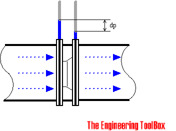
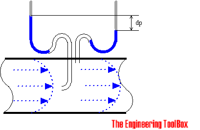
In a differential pressure drop device the flow is calculated by measuring the pressure drop over an obstructions inserted in the flow. The differential pressure flowmeter is based on the Bernoullis Equation, where the pressure drop and the further measured signal is a function of the square flow speed.


The most common types of differential pressure flowmeters are:
  • Orifice Plates
  • Flow Nozzles
  • Venturi Tubes
  • Variable Area - Rotameters

Orifice Plate

With an orifice plate, the fluid flow is measured through the difference in pressure from the upstream side to the downstream side of a partially obstructed pipe. The plate obstructing the flow offers a precisely measured obstruction that narrows the pipe and forces the flowing fluid to constrict.


The orifice plates are simple, cheap and can be delivered for almost any application in any material.

The TurnDown Rate for orifice plates are less than 5:1. Their accuracy are poor at low flow rates. A high accuracy depend on an orifice plate in good shape, with a sharp edge to the upstream side. Wear reduces the accuracy.

Venturi Tube

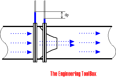
Due to simplicity and dependability, the Venturi tube flowmeter is often used in applications where it's necessary with higher TurnDown Rates, or lower pressure drops, than the orifice plate can provide.

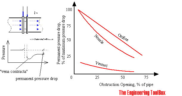
In the Venturi Tube the fluid flowrate is measured by reducing the cross sectional flow area in the flow path, generating a pressure difference. After the constricted area, the fluid is passes through a pressure recovery exit section, where up to 80% of the differential pressure generated at the constricted area, is recovered.


With proper instrumentation and flow calibrating, the Venturi Tube flowrate can be reduced to about 10% of its full scale range with proper accuracy. This provides a TurnDown Rate 10:1.

Flow Nozzles

Flow nozzles are often used as measuring elements for air and gas flow in industrial applications.

The flow nozzle is relative simple and cheap, and available for many applications in many materials.
The TurnDown Rate and accuracy can be compared with the orifice plate.

The Sonic Nozzle - Critical (Choked) Flow Nozzle

When a gas accelerate through a nozzle, the velocity increase and the pressure and the gas density decrease. The maximum velocity is achieved at the throat, the minimum area, where it breaks Mach 1 or sonic. At this point it's not possible to increase the flow by lowering the downstream pressure. The flow is choked.

This situation is used in many control systems to maintain fixed, accurate, repeatable gas flow rates unaffected by the downstream pressure.

Recovery of Pressure Drop in Orifices, Nozzles and Venturi Meters

After the pressure difference has been generated in the differential pressure flow meter, the fluid pass through the pressure recovery exit section, where the differential pressure generated at the constricted area is partly recovered.


As we can see, the pressure drop in orifice plates are significant higher than in the venturi tubes.

Variable Area Flowmeter or Rotameter

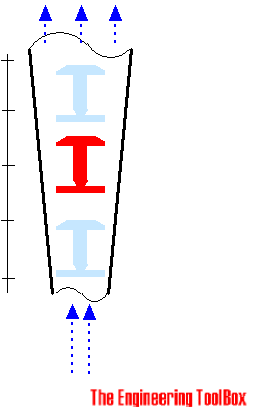
The rotameter consists of a vertically oriented glass (or plastic) tube with a larger end at the top, and a metering float which is free to move within the tube. Fluid flow causes the float to rise in the tube as the upward pressure differential and buoyancy of the fluid overcome the effect of gravity.


The float rises until the annular area between the float and tube increases sufficiently to allow a state of dynamic equilibrium between the upward differential pressure and buoyancy factors, and downward gravity factors.

The height of the float is an indication of the flow rate. The tube can be calibrated and graduated in appropriate flow units.

The rotameter meter typically have a TurnDown Ratio up to 12:1. The accuracy may be as good as 1% of full scale rating.

Magnetic floats can be used for alarm and signal transmission functions.


Velocity Flowmeters

In a velocity flowmeter the flow is calculated by measuring the speed in one or more points in the flow, and integrating the flow speed over the flow area.


Pitot Tubes

The pitot tube are one the most used (and cheapest) ways to measure fluid flow, especially in air applications as ventilation and HVAC systems, even used in airplanes for the speed measurent.


The pitot tube measures the fluid flow velocity by converting the kinetic energy of the flow into potential energy.

The use of the pitot tube is restricted to point measuring. With the "annubar", or multi-orifice pitot probe, the dynamic pressure can be measured across the velocity profile, and the annubar obtains an averaging effect.

Calorimetric Flowmeter

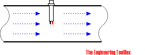
The calorimetric principle for fluid flow measurement is based on two temperature sensors in close contact with the fluid but thermal insulated from each other.


One of the two sensors is constantly heated and the cooling effect of the flowing fluid is used to monitor the flowrate. In a stationary (no flow) fluid condition there is a constant temperature difference between the two temperature sensors. When the fluid flow increases, heat energy is drawn from the heated sensor and the temperature difference between the sensors are reduced. The reduction is proportional to the flow rate of the fluid.

Response times will vary due the thermal conductivity of the fluid. In general lower thermal conductivity require higher velocity for proper measurement.

The calorimetric flowmeter can achieve relatively high accuracy at low flow rates.

Turbine Flowmeter

There is many different manufacturing design of turbine flow meters, but in general they are all based on the same simple principle:

If a fluid moves through a pipe and acts on the vanes of a turbine, the turbine will start to spin and rotate. The rate of spin is measured to calculate the flow.

The turndown ratios may be more than 100:1 if the turbine meter is calibrated for a single fluid and used at constant conditions. Accuracy may be better than +/-0,1%.

Vortex Flow Meter

An obstruction in a fluid flow creates vortices in a downstream flow. Every obstruction has a critical fluid flow speed at which vortex shedding occurs. Vortex shedding is the instance where alternating low pressure zones are generated in the downstream.


These alternating low pressure zones cause the obstruction to move towards the low pressure zone. With sensors gauging the vortices the strength of the flow can be measured.

Electromagnetic Flowmeter

An electromagnetic flowmeter operate on Faraday's law of electromagnetic induction that states that a voltage will be induced when a conductor moves through a magnetic field. The liquid serves as the conductor and the magnetic field is created by energized coils outside the flow tube.

The voltage produced is directly proportional to the flow rate. Two electrodes mounted in the pipe wall detect the voltage which is measured by a secondary element.

Electromagnetic flowmeters can measure difficult and corrosive liquids and slurries, and they can measure flow in both directions with equal accuracy.

Electromagnetic flowmeters have a relatively high power consumption and can only be used for electrical conductive fluids as water.

Ultrasonic Doppler Flowmeter

The effect of motion of a sound source and its effect on the frequency of the sound was observed and described by Christian Johann Doppler.

The frequency of the reflected signal is modified by the velocity and direction of the fluid flow

If a fluid is moving towards a transducer, the frequency of the returning signal will increase. As fluid moves away from a transducer, the frequency of the returning signal decrease.

The frequency difference is equal to the reflected frequency minus the originating frequency and can be use to calculate the fluid flow speed.

Positive Displacement Flowmeter

The positive displacement flowmeter measures process fluid flow by precision-fitted rotors as flow measuring elements. Known and fixed volumes are displaced between the rotors. The rotation of the rotors are proportional to the volume of the fluid being displaced.

The number of rotations of the rotor is counted by an integral electronic pulse transmitter and converted to volume and flow rate.

The positive displacement rotor construction can be done in several ways:

  • Reciprocating piston meters are of single and multiple-piston types.
  • Oval-gear meters have two rotating, oval-shaped gears with synchronized, close fitting teeth. A fixed quantity of liquid passes through the meter for each revolution. Shaft rotation can be monitored to obtain specific flow rates.
  • Nutating disk meters have moveable disks mounted on a concentric sphere located in spherical side-walled chambers. The pressure of the liquid passing through the measuring chamber causes the disk to rock in a circulating path without rotating about its own axis. It is the only moving part in the measuring chamber.
  • Rotary vane meters consists of equally divided, rotating impellers, two or more compartments, inside the meter's housings. The impellers are in continuous contact with the casing. A fixed volume of liquid is swept to the meter's outlet from each compartment as the impeller rotates. The revolutions of the impeller are counted and registered in volumetric units.
The positive displacement flowmeter may be used for all relatively nonabrasive fluids such as heating oils, lubrication oils, polymer additives, animal and vegetable fat, printing ink, freon, and many more.

Accuracy may be up to 0.1% of full rate with a TurnDown of 70:1 or more.

Mass Flowmeters

Mass meters measure the mass flow rate directly.

Thermal Flowmeter

The thermal mass flowmeter operates independent of density, pressure, and viscosity. Thermal meters use a heated sensing element isolated from the fluid flow path where the flow stream conducts heat from the sensing element. The conducted heat is directly proportional to the mass flow rate and the he temperature difference is calculated to mass flow.

The accuracy of the thermal mass flow device depends on the calibrations reliability of the actual process and variations in the temperature, pressure, flow rate, heat capacity and viscosity of the fluid.

Coriolis Flowmeter

Direct mass measurement sets Coriolis flowmeters apart from other technologies. Mass measurement is not sensitive to changes in pressure, temperature, viscosity and density. With the ability to measure liquids, slurries and gases, Coriolis flowmeters are universal meters.

Coriolis Mass Flowmeter uses the Coriolis effect to measure the amount of mass moving through the element. The fluid to be measured runs through a U-shaped tube that is caused to vibrate in an angular harmonic oscillation. Due to the Coriolis forces, the tubes will deform and an additional vibration component will be added to the oscillation. This additional component causes a phase shift on some places of the tubes which can be measured with sensors.

The Coriolis flow meters are in general very accurate, better than +/-0,1% with an turndown rate more than 100:1. The Coriolis meter can also be used to measure the fluids density.

Open Channel Flowmeters

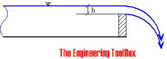
A common method of measuring flow through an open channel is to measure the height of the liquid as it passes over an obstruction as a flume or weir in the channel.


Common used is the Sharp-Crested Weir, the V-Notch Weir, the Cipolletti weir, the Rectangular-Notch Weir, the Parshall Flume or Venturi Flume.

Multiphase flow pattern and Flow pattern maps

The behavior and shape of the interfaces between phases in a multiphase mixture dictates what is referred to as the ‘flow regime’ or the ‘flow pattern’. 

There are competing forces or mechanisms occurring within the multiphase fluid at the same time. The balance between these forces determines the flow pattern.

Factors dictating the flow pattern of a multiphase flow in a conduit are - 
  • Phase properties, fractions and velocities.
  • Operating pressure and temperature.
  • Conduit diameter, shape, inclination and roughness.
  • Presence of any upstream or downstream pipe work (e.g. bends, valves, T-junctions).
  • Type of flow: steady state, pseudo steady state or transient.
Flow pattern classifications were originally based on visual observations of two-phase flow experiments in the laboratory. The experimental observations were mapped on 2D plots called ‘flow-pattern maps’.

The factors governing the interfacial distribution (flow regimes) in a gas– liquid flow include -
  • surface tension, 
  • wetting, 
  • dispersion,
  • coalescence, 
  • body forces and 
  • heat flux effects. 
There various flow regimes range from 100% liquid to 100% gas and are associated with the pipe orientation (i.e. horizontal versus vertical) due to the ever-present effects of the earth’s gravity.

Flow Regimes for Horizontal Pipe


The regimes in Horizontal gas–liquid flows are illustrated in Figure above . The regimes are as follows:
  • Bubble flow - the phase is composed of bubbles dispersed in the liquid phase. However, due to the effect of buoyancy forces on the bubbles, they tend to accumulate in the upper part of the pipe.
  • Stratified flow - This regime occurs when the gravitational separation is complete. The liquid flows along the bottom of the tube and the gas along the top part of the tube.
  • Stratified Wavy flow - As the gas velocity is increased in stratified flow, waves are formed on the gas–liquid interface giving the wavy or stratified-wavy flow regime.
  • Plug flow - Horizontal plug flow is characterized by bullet-shaped bubbles.These bubbles tend to flow along the top of the tube due to buoyancy forces.
  • Slug flow - There are large (often frothy) surface waves signifying a large fluctuation in liquid delivery along the pipe. This regime is characterised by the passage along the channel of frothy ‘slugs'.
  • Annular flow - The liquid flows on the wall of the tube as a film and the gas flows in the center. The liquid film tends to be much thicker at the base of the tub.
    Flow regimes for a Vertical Pipe

    The regimes in vertical gas–liquid flows are illustrated in Figure above. The regimes are as follows.
    1. Bubble flow - Here, the liquid phase is continuous and a dispersion of bubbles flows within the liquid continuum. The bubbles are subject to complex motion within the flow, maybe coalescing, and are generally of non-uniform size.
    2. Slug (or plug) flow - This flow pattern occurs when the bubble size is that of the channel, and characteristic bullet-shaped bubbles are formed, often interspersed with a dispersion of smaller bubbles.
    3. Churn flow - At higher flow velocities, the slug flow bubbles breakdown leading to an
      unstable flow regime in which there is, in wide bore tubes, an oscillatory motion of the liquid, hence the name churn flow.
    4. Annular flow - Here, the liquid flows on the wall of the tube as a film and the gas flows in the centre. Usually, some of the liquid phase is entrained as small droplets in the core; at high flows, it is also common for bubbles of gas to be entrained in the liquid film.
    Horizontal and Vertical Flow Maps - 

    Horizontal Flow Map

    Vertical Flow Map


    Even a very small variations in pipe inclination can cause important variations in the flow pattern map of a given mixture, all the rest staying the same.


    What is Multiphase Flow

    As a general definition - Two or more phases flowing simultaneously in a closed conduit is referred to as Multiphase Flow.

    Multiphase flows are the most common flow occurrences in nature. Examples are the flow of blood in the human body, the bubbles rising in a glass of cold beer and the steam condensation on windows.

    The simplest case of multiphase flow is -  of a two-phase flow in which the same pure component is present in two different phases. An example - a steam-water flow.

    On the other hand, if different chemical substances co-exist, the flow is usually referred to as multicomponent. This is the case of an air–water flow (two-phases, two components).

    Multiphase measurement is a catch of all term that describes multiple fluid components in a flowing stream. For instance, water and oil are considered to be multiphase in the oil and gas industry, even though they are both liquids.

    The phases present in a multiphase flow are composed of:
    1. Solids, which are normally in the form of relatively small particles. The solid phase is incompressible and has non-deformable interfaces with the surrounding fluids.
    2. Liquids, which are also relatively incompressible, but their interfaces with the other phases are deformable.
    3. Gases, where the phase is compressible and deformable
    Some common class of two phase multiphase flows are -
    • Gas–solid flows - solid particles are suspended in gases.
    • Liquid–liquids flows -  emulsion flows of oil and water in pipelines.
    • Liquid–solid flows - Suspensions of solids in liquids.
    • Gas–liquid flows - Gas flowing with oil and/or water
    Three-phase flows examples being as follows -
    • Gas–liquid–solid flows - found in froth flotation as a means of separating minerals.
    • Gas–liquid–liquid flows -  oil, water and natural gas.
    • Solid–liquid–liquid flows - occur if sand was mixed with oil and water in the pipeline
    The four-phase flow example can be - a oil–water–gas–sand mixture

    The types of multiphase flow which are of interest foe the Oil and Gas Industry are -
    • gas–liquid flows (oil–natural gas), 
    • liquid–liquid flows (oil–water), 
    • gas–liquid–liquid flows (natural gas–oil–water) and 
    • solid–liquid–liquid–gas flows (sand–oil–water–natural gas)..

      Growth of Multiphase Meters and the Key Challenges they are Addressing

      By - Vincent Vieugue,
      Emerson Process Management

      The Multiphase Meter Market Today

      There is no doubt that the market for multiphase meters within the oil and gas industry is continuing to grow.
      Douglas Westwood, for example, predicts that there will be one thousand additional subsea multiphase meters deployed by 2015 and many operators are continuing the rapid deployment of such meters – both subsea and topside. Examples include Petrobras, who have indicated that they would like to see a multiphase meter on each of their subsea wells and trees; and Statoil, one of the first users of the technology, which today has more than 150 multiphase and wet gas meters in operation.

      Multiphase meters are today a vital component of operators’ development and field production plans. They can be used for production monitoring, individual well testing, production allocation and reservoir monitoring and they provide the operator with critical information on a well’s capabilities – information such as water saturation and break through, gas coning, permeability and flow characteristics.

      Yet, there is plenty more room for growth. According to Rystad Energy Global, just 12% of global oil & gas production is currently facilitated by multiphase meters.

      From 1st to 3rd Generation

      In order to understand the current adoption of multiphase meters and their future potential, it is necessary to examine how they have developed. Multiphase meters have undergone a significant evolution since they first came on the market in the early 1990’s. The first commercial Roxar topside multiphase meter, for example, (launched in 1992) was based on microwave technology, operated on a single velocity basis, and assumed that homogenous flow and liquid and gas were travelling at the same speed.

      In the early 2000’s, the second generation multiphase meters came to market (figure 1 shows a subsea version of the Roxar second generation meter). The meter allowed, for the first time, measurement of both liquid and gas velocities. The meter incorporated a Dual Velocity™ method with calculated phase fractions based on capacitance and conductivity measurements. The meter also came in combination with a single energy gamma densitometer and venturi section.

      Other highlights of the second generation meter included parts designed to withstand more than 30 years of operating in harsh environments, power consumption at less than four times that of the first generation meter, and for subsea meters, a retrievable canister.

      By this stage, the benefits to the operator were also clear. This included no separation requirements; no need for costly test separators; the instantaneous and continuous measurement of three phase rates – not just at a discrete point in time and not just for one well; and limited maintenance requirements. The result was substantial CAPEX/OPEX savings, increased well control, and enhanced production from the fields.

      Changing Operator Needs

      However, as multiphase meters continue to increase their market penetration, so do the challenges increase. Many oil & gas fields, for example, are more geologically complex, remote and heterogeneous than ever before. There is an even greater need for multiphase meters to generate accurate and reliable, real-time data from the wells to help diagnose and optimize the well’s performance and fend off flow assurance threats.

      Such a need can’t necessarily be met by the second generation multiphase meter’s measurement principle which provides a simplification of complex flow patterns and is dependent on the reservoir being relatively homogeneous.

      Secondly, the last few years have seen a growth in smaller fields (on average 200 to 300 million bbl) as well as brownfields. Only recently, Statoil announced that it is to focus further on brownfields to sustain production on the Norwegian Continental Shelf (NCS) at current levels.

      Multiphase meters have an important role to play in brownfield developments in improving well testing in environments characterized by often complex interdependencies between aging and new technologies. There is also a subsequent need for an even simpler and compact meter design, which helps widen the operating envelope, increase flexibility, and lower the cost per meter.

      Finally, there is the need to meet environmental and HSE requirements, particularly where the use of nucleonic sources is unacceptable, due to legislation or company policy. The ability for operators to forgo the nucleonic source within multiphase meters without forgoing accuracy remains a continuing challenge.

      In summary, while second generation meters continue to be successful and effective, there is an increased onus on multiphase meters for even greater accuracy and a measurement principle that enables the operator to better handle complex, flow regimes and achieve maximum production rates.

      There is also a need for multiphase meters to take on board environmental implications, widen the operating envelope, and operate at lower costs and in previously inaccessible locations.

      The Third Generation Multiphase Meter

      So how can the third generation multiphase meter (see figure 2) address these challenges?


      The development of a new electrode geometry sensor for the meter, for example, can allow for measurements in separate sectors in addition to the full cross sectional area. This results in more combinations and more accurate fraction measurements and velocities for each segment.

      Rather than being able to perform cross sectional measurements, the new measurement principle will allow the meter to perform both rotational near wall measurements and cross-volume measurements, thereby providing a comprehensive mapping of the flow regimes. Asymmetrical flow and less-than-perfect mixtures of the gas and dispersed phase can also be handled in a manner that was impossible with previous meters. The measurement principle is shown below in figures 3a and 3b (red indicates high sensitivity, blue indicates low sensitivity).


      In this way, the operator can benefit from an accurate understanding of flow regimes, mixing effects and velocity profiles, and can detect rapid changes in compositon, thereby making the measurements more accurate and consistent than with other available technology.

      There is also the potential for widening the operating envelope with the next generation of multiphase meters. This can be achieved through reduced height and weight, opening up substantial potential cost savings in terms of installation, maintenance and deck space.
      Field Replaceable Insert Venturis also allow for extended service life and operating range, and can remove uncertainties in sizing meters based on uncertain production forecasts.
      A meter with several Field Replaceable Insert Venturi sizes, for example, means that the optimal size can be selected for early life and replaced later with a different size in late production life. In this way, optimal performance from the venturi can be achieved.

      Finally, there is the challenge of alleviating environmental concerns. To counteract concerns over nucleonic sources, non-radioactive meters can today cover the full operating range 0 -100% watercut and 0 – 95% GVF (gas volume fraction).

      However, for those operators who are concerned with the limitations over the maximum GVF range or the slightly higher uncertainty than the gamma version, developments are underway in Emerson’s case to develop a densitometer based on X-rays as an alternative to the nucleonic gauge.

      The X-ray based densitometer, known as FluorX and developed in conjunction with PANalytica, utilizes attenuation measurements of the same photon energies as a low energy gamma-ray source, and provides the same measurement accuracy. Adding a FluorX system to the non-gamma meter version means that the meter can be used in the full 0-100% GVF range and also ensures improved accuracy, as our tests have shown.

      Much More to Come!

      With the market for multiphase meters continuing to grow and the need for accurate flow measurement and a wider operating envelope as important as ever, it is imperative that today’s multiphase meters are able to meet operator challenges.

      A new measurement principle, new electrode geometry and near wall measurements are ensuring that multiphase meters continue to evolve to meet such demands.

      Such technical developments, as well as meeting environmental concerns through developments, such as the x-ray based densitometer, will ensure that multiphase metering becomes ever more prevalent – not just in well testing but in reservoir monitoring, flow assurance calculations, and production optimization.

      Vincent Vieugue is Vice President of Sales & Marketing at Roxar Flow Measurement, part of Emerson Process Management.

      Source - ROGTEC-Magazine   -   View Original Article


      RESERVOIR MONITORING: Multiphase meter on unmanned wellhead platform replaces test separators


      The skid mounted multiphase meter.

      At the beginning of the 1990s, a major research and development project to extend the capabilities of multiphase export was launched. This program included the simultaneous development of multiphase flow modeling, multiphase technology (qualification of multiphase pumps, development of multiphase meters, and subsea separation), and a new process to fight fluid-related effects such as hydrates, waxes, and others.

      The initial aim was to simplify surface topside facilities, and to avoid installation of separators, pumps, compressors, and safety/flaring systems. In a second stage, this technology could be subsea deployed. The development of these different disciplines would help to avoid duplicate processing and huge infrastructures, and would ease remote controlled operation of unmanned platforms. The multiphase meter was one component of this global approach.

      From 1991 to 1996, TotalFinaElf supported and tested multiphase meter prototypes. These were qualified on onshore fields. The application of an integrated multiphase approach to develop a Middle East offshore field reduced the investments and operating costs drastically.

      In such a development, the multiphase meter found its place by eliminating the need for a dedicated testing flowline or a test separator and flaring system. Therefore, in 1997, their first multiphase meter on an offshore-unmanned wellhead platform was installed.

      Meter application

      The decision to use a multiphase meter was made in 1994-1995. Very few fields relied on a multiphase meter for well testing, without it being backed up by a test separator. The field layout comprises wells that are clustered on a wellhead platform. The production is sent to shore through a 40 km line. After separation, the oil is metered before custody transfer, which yields an excellent reference measurement.

      The platform is unmanned. It has minimum facilities - production manifold, test manifold, and multiphase flowmeter (MPFM) 1900VI. The local operator interface of the meter is housed in the electrical room. The readings from the meter are also available onshore, through a low baud rate communication that carries all the control signals for the platform. The valves of the test manifold are not equipped with actuators.

      Benefits

      The field comprises several wells that are clustered on a wellhead platform. The production is sent on shore by a 40 km pipeline.


      Monitoring of the multiphase flow at the wellhead eliminates the need for dedicated test lines from remote wellhead completions, as well as the need for a dedicated test separator at the processing facility. The meter replaces a test separator in its functionality.

      A MPFM at the wellhead allows improved well control, hence better reservoir monitoring and well performance management. It is clear that extra information could be gained from the instantaneous feature of the measurement. For example, water slugs and gas slugs appear clearly in the readings of the remote wells. Continuous readings, instead of accumulated quantities given by test separator, will allow diagnostics of well behavior, and total recovery would probably be increased.

      The capital expenditure savings have been estimated at US$800,000, compared to a test separator solution. In this application, the main savings came from the fact that the device saved the cost of the flare. The platform has no vessels to blow down.

      This device helps in cutting operating expenditures as well. Despite the manually operated valves of the manifolds, it is possible to have each well tested monthly with only one visit per week. During a one-day visit, the production operator can test 2-3 wells, thanks to the short stabilization time of the meter. When leaving, the operator launches a 'long' test that will last until the next visit. A remote display allows for further analysis of the behavior of a given well. From a maintenance point of view, the meter is a low maintenance cost item, compared to a test separator.

      Description

      The multiphase meter is basically an instrumented pipe section, approximately 1.4 meters long, and consists of a capacitance sensor, an inductive sensor, a gamma densitometer, and a venturimeter. In addition, there is a flow computer and a service console.


      The multiphase meter used for this application is basically an instrumented pipe section, approximately 1.4 meters long, and with an internal diameter of 3 in. No separation and mixing is involved. The meter has been supplied as skid mounted, complete with inlet and return piping, with drain, vent, and drip tray for ease of calibration.

      In order to limit any potential for clogging by wax and other materials within the meter itself, or in the pressure and differential pressure impulse lines, the complete instrumented pipe section has been heat-traced and lagged.

      The multiphase meter is a Fluenta MPFM 1900VI, and consists of a capacitance sensor, an inductive sensor, a gamma densitometer, a venturimeter and a flow computer. The measurement principle is first to measure the density of the flow using a gamma densitometer. In oil-continuous flow (up to 60-70% water cut), the density measurement is combined with a measurement of the dielectric constant of the flow using the non-intrusive, surface plate, and capacitance sensor. Together, these two measurements provide the instantaneous composition of the flow at the measurement location.

      At higher water cut, when water is the continuous liquid phase, the mixture conductivity is measured using an inductive type sensor. This then replaces the capacitance measurement in the composition calculation.

      The velocity of the flow is determined by cross-correlation between different electrode pairs in the capacitance sensor. The cross correlation velocity may also be combined with the venturi meter, which extends the range of the multiphase meter to cover single phase liquid and annular flow, and also add redundancy to the velocity measurement in the intermediate range of gas volume fraction (GVF).

      By combining both the compositional and the velocity information of the flow, the actual flow rates of oil, gas and water are determined by mathematical models hosted in the flow computer. The interphasial slip between liquid and gas is handled using the Dual Velocitytrademark method. This method is capable of handling complex flow regimes, including severe slugging, in-homogeneous phase distribution, and interphasial slip.

      The non-intrusive design, together with the Dual Velocity method for handling phase slip, means the Fluenta multiphase meters do not require mixers to homogenize the flow, or a separator to split the flow, before measurement. This gives the meter a wide operating range, which is not limited by the efficiency of the upstream flow conditioner or splitter. Due to the limited interaction with the flow, pressure drop, erosion, and creation of emulsions that may otherwise affect the downstream process, are avoided.

      Operational experience

      The MPFM 1900VI was offshore commissioned in early 1997. Fluenta carried out this job with assistance from in-house specialists, especially for fluid parameters (oil and water density) determination. The duration of the commissioning/startup phase was about 10 days including training for the operators.

      No test separator was available on the offshore platform for testing and verification. A static calibration procedure has been defined and implemented. This has been successfully applied to the meter to check the meter and make diagnostics. The procedure involves isolating the meter, emptying it and filling it with air, oil, and seawater. Since the fluid properties are known, this makes it possible to check the static response and calibration of the capacitance sensors, inductance sensor and gamma meter.

      The MPFM is continuously in operation. During the weekly visit, wells to be tested are switched through the meter. A well test takes about one hour, and all the tests are validated before being entered into the database. In between weekly visits, the MPFM is left under flowing conditions with one well producing through the meter.

      The man machine interface allows simple operation of the system. No systematic maintenance is carried out under normal operation. Verification of performance is done through regular follow up and comparison between well figures and total production.

      The manufacturer has been called out once a year for calibration, and once for replacement of a display monitor and an electronic card on the inductive sensor. In four years, three interventions have been carried out by the manufacturer, mainly for capacitance and inductance sensors calibration.

      The system has been operating successfully during four years without any problems. No failure has been recorded on sensors. The availability has been 100% since startup. The meter has been used during a short period of time only for liquid and gas measurements, due to a bias in the water cut measurement generated by incorrect water cut setting.

      This indicates that care must be taken when calibrating MPFM with field measurements, which are not necessarily representative. This also indicates that even in such a case, the system still continues to provide data before reconfiguration or recalibration of some sensors.

      The meter has been used for continuous recording of flow rates, gas fraction, and water hold up of wells for well behavior monitoring or for individual well test for reservoir management. Accuracy of the meter has been checked by both daily and monthly comparison with terminal figures. MPFM figures for oil and water have been in good agreement (average of less than +/-5% for oil, and +/-10% relative for water) with fiscal figures. Yearly figures show a difference of less than 1% between reference figures and multiphase meter figures.

      Conclusion

      The decision to install a multiphase flow meter instead of a test separator was governed by the low cost of such a development compared to alternative solutions. We have to recognize that the qualification was still in its final phase when the decision was made. The deployment of this equipment has allowed the unmanned operation of this platform. This technology has allowed a step-by-step approach. Today, additional multiphase flow meters have been ordered in the frame of an extension of the development.

      Compared to the results we are accustomed to getting from a test separator, the figures, which are delivered by this equipment, are in the same range of accuracy. Furthermore, the detailed analysis of the gas/water/oil fraction distribution allows better knowledge of the flow conditions in the gathering system and in the flowlines. During transient operations (mainly startup operations), the increase of the water cut allows us to improve our understanding of the well near the well bore.

      On this field, the deployment of a multiphase meter has contributed in improving the economy of the full project and improving our understanding of the hydrodynamics of the reservoir near the wellbore.

      This experience demonstrates that the MPFM can be a very reliable solution for well testing and well monitoring; nevertheless success requires involvement of all people (project people, specialists, users) from design studies to operations. Also, support of manufacturers and a mutual understanding are key issues. Four years life time without failure shows that multiphase metering is now compatible with very demanding subsea and high water depths applications (sequences, tests, long term checks, cost impact).

      References

      Leggett B. et. al, "Multiphase Flow Meter Successfully Measures Three-Phase Flow at Extremely High Gas Volume Fractions - Gulf of Suez, Egypt," SPE 36837.
      Caetano, E., Pinheiro, J., Moreira, C., Farestvedt, R., "MMS 1200 - Cooperation on a Subsea Multiphase Meter Application," OTC 8506.
      Slater, S., Paterson, A., Marshall, M., "The development and use of a subsea multiphase flowmeter on the South Scott Field," OTC 8549.
      Razali I., "Multiphase metering in Malaysia - Current and Future," 4th Annual International Conference - The future of multiphase metering.
      Perry, D., Mitchell, M., Halvorsen, M., "Application of the First Multiphase Flow Meter in the Gulf of Mexico," SPE 49118.
      Dykesteen, E., "Comparison of experiences from Multiphase Metering in different operations," IBC 1999.
      Egner, E., Kalsaas, O., "Operational experience with multiphase meters at Vigdis," North Sea Flow Measurement Workshop, 1999.
      Caetano, E., Dykesteen, E., "Operational experience with subsea multiphase meter," North Sea Flow Measurement Workshop, 2000.

      Editor's Note: This is an updated and summarized version of OTC 13220, presented at the Offshore Technology Conference in Houston, Texas, May 2001.
       

      Present Status of MultiPhase Metering in Oil and Gas Industry

      Multiphase metering technology has advanced significantly in recent years, as has the acceptance and utilisation of such technology offshore. Dr David Stewart, NEL's multiphase flow services manager, reviews the current state of play and highlights the developments and challenges ahead.

      Many new field developments are economically marginal and cannot sustain the financial implications of the traditional separatorbased technology. Multiphase meters can offer significant cost savings by eliminating the need for separators, or by allowing several fields to share common processing facilities.

      In well management applications, multiphase meters offer continuous data output giving valuable information about the performance of wells. This enables problems or changes in well performance to be detected sooner, and subsequent decisions to be made earlier than would be possible with traditional processing technology.

      The importance of multiphase metering is evident in the number of papers published on the subject and the time devoted to it at major flow measurement and oil and gas conferences. This was the case at October's North Sea Flow Measurement Workshop, a major event organised by NEL which attracted over 250 engineers from the oil and gas industry.

      In-line multiphase meters
      In-line multiphase meters rely on a number of fluid property measurements combined to give the flowrate of each of the three phases, oil, water, and gas. There are several techniques employed, although these can be grouped into two key areas - velocity or total flow measurement and phase fraction measurement.

      Velocity/flow measurements are most commonly achieved using a differential pressure measurement or cross correlation of a particular signal, ie pressure or conductivity. Many meters also use slip models, which accounts for the fact that the gas generally travels faster than the liquid. Some in-line meters try to minimise slip by trying to homogenise the flow using a blind tee upstream of the meter with the meter installed in a vertical upwards flow direction.

      The phase fractions can be determined from measurements of physical properties of the three-phase mixture from which the relative quantities of each individual phase can be deduced.

      Gamma energy attenuation is a common method, where the oil, water and gas attenuate the gamma energy by different amounts. The gamma energy is emitted at two energy levels, as the high energy level is more sensitive to the gas/liquid ratio and the lower energy is more sensitive to the water/oil ratio in the liquid phase. Combined, the two energy attenuation measurements can be used to determine the phase fraction of all three phases. A third energy level can also be used to determine the salinity of the water phase.

      The capacitance/conductance technique can be used to determine the water cut in the liquid phase. In oil continuous flow a capacitance sensor is used to measure the dielectric constant of the fluid and determine the water cut. In water continuous flow a conductance sensor is used. This approach can be good at high gas volume fractions. The disadvantages are that if the fluid is continually switching between oil continuous and water continuous the meter can find it difficult to track the changes.

      Microwave attenuation can also be used to measure the water cut in the liquid phase. This has the benefit of being less sensitive to GVF and works in both oil and water continuous flows.

      Many years of testing at NEL and in the field has shown that in-line meters can achieve accuracies of between 2.5% and 10% at best on each phase at certain conditions, although performance can vary significantly with GVF and water cut. Other parameters such as pressure, liquid viscosity and water salinity can also significantly affect the performance.

      Separation based meters
      Separation based meters or systems can employ various degrees of separation, but most use compact separators to achieve partial separation. This results in a predominantly liquid stream containing up to 30% gas by volume and a gas stream usually containing no more than 1% or 2% liquid by volume, but can in extreme cases, particularly in heavy slug flow, contain up to 10% liquid by volume.

      Generally, compact cyclone separators are used for the separation, with the liquid level adjusted using flow control valves on the inlet and outlets. Most separation-based meters use a standard in-line multiphase meter on the predominantly liquid stream and a standard gas meter, such as a vortex or Coriolis meter, on the gas stream. If there is a high liquid content in the gas stream a wet gas meter that is capable of measuring both liquid and gas flowrates can be used.

      Tests in recent years, again at NEL and in the field have shown that separation based systems can achieve better than 5% accuracy on each phase and are less affected by GVF than in-line meters. The main disadvantages are the size, weight and reliance on fast acting valves for level control in the separator. This can make them unsuitable for subsea applications.

      Performance verification
      The discussion regarding the most suitable means of verifying multiphase meter performance has continued for many years. The simplest option is to do nothing and hope the meter performs. Given the complexity of the instrumentation and software and, depending on the application, the potential financial implications of meter errors or failure, this approach is not recommended.

      The next option is to rely on a basic functionality test carried out by the meter vendor. This could be as simple as confirming that the meter can recognise static samples of oil, water and gas, or could involve a more involved flow test using the vendor's flow facility. Many users are understandably reluctant to accept such tests as proof of performance due to the lack of independence.

      Consequently, it is common to conduct a flow test at an independent test facility. NEL has carried out many such acceptance tests over recent years for many clients in its multiphase flow test facility. This facility was purpose built just over ten years ago for multiphase meter evaluation and testing. The advantage of a trusted independent facility is that the reference metering will be accurate and fully traceable and that the independent organisation has no affiliation to either the vendor or the end user.

      There is also the debate over what type of test fluids to use. The use of 'dead' fluids where the gas does not dissolve in the oil and there is no phase change with pressure or temperature is the practice at NEL, with the advantage that it allows NEL to achieve low uncertainties on the reference flowrates. Some argue that the disadvantage is that the fluids do not replicate those in the field.

      The use of 'live' crude oil and natural gas is more realistic but means that the gas is highly soluble in the oil, making reference metering difficult. If the test meter is at a different pressure and/or temperature from the reference meters then the gas can go into or come out of solution with the oil. This change in phase fraction within the test facility must be accounted for by either complex physical PVT analysis of the oil and gas, or by modelling the PVT behaviour if the fluid properties are known. Either way, the inevitable result is a higher uncertainty in the reference flowrates.

      It is also common to verify a meter offshore against a three-phase test separator when such facility exists. This does have the advantage of testing the meter in its intended installation using the fluids it will be metering in practice. However, the significant disadvantage of this approach is the potentially high uncertainty in the reference flowrates. The separator performance can have a major effect on the metering accuracy. Liquid carry over or gas carry under, resulting from poor separation, can result in large errors in the liquid and gas flowrates, in addition to the added uncertainty of using live fluids.

      These issues are discussed in a paper from the recent North Sea Flow Measurement Workshop, which describes the meter selection and verification process for three multiphase meters for Kerr-McGee North Sea (UK). In this one meter was verified at NEL and subsequently against the test separator offshore. The other two meters were tested using live fluids at ChevronTexaco's Humble facility with NEL acting as independent witnesses.

      Multiphase meter challenges
      The challenges for multiphase metering at present are several. Cost reduction is a key aim as some of the meters on the market are very expensive. Another paper from the North Sea Flow Measurement Workshop, presented by Shell, highlighted this fact, discussing the desire for a multiphase meter per well for improved well management. At present most multiphase meters are too expensive for this to be a real consideration, however the paper highlighted work that Shell has been doing in conjunction with a manufacturer of a low cost meter that could be considered for 'per well' metering.

      A key aspect was this meter's lack of a nuclear source for density measurement. In many parts of the world such sources are either not allowed, or simply not desirable due to the risk of sabotage. An upcoming NEL research project, funded by the UK's DTI, will investigate the suitability of an ultrasonic based multiphase meter.

      Improved accuracy is obviously another key aim, as an increasing number of applications will call for multiphase meters to be used for allocation purposes between different oil companies. In such cases the uncertainty in the oil phase, and possibly gas phase would be critical.

      A slightly longer term challenge is the development of downhole meters. These meters would operate in the actual well and provide valuable information on which areas of the well are producing which fluids. This would enable improved well management and faster, more accurate decisions regarding well production. Several manufacturers are actively developing downhole meters at present. The key issue for such meters is reliability in an extreme environment.

      Source: OilOnline.com   -   View Original Article


      Commingled multiphase flows – the metering challenge


      Metering and allocation of the oil and gas industry is more complicated than ever. Production flows are no longer straightforward. Instead, various streams made up of differing mixes of oil, water, and gas from different fields belonging to different operators and sometimes even under different tax regimes, are being commingled as an increasing number of marginal fields enter production.

      A new approach to metering is required and “per-well” multiphase meters appear to be the best way. But, is the technology ready? Meter manufacturers believe so, but TUV NEL, which has performed independent testing of multiphase meters over the past 20 years, believes more testing and verification is required to give field operators the confidence and experience to meet their commitment to partners and regulatory bodies.

      Most offshore fields developed 20 or 30 years ago were designed to cope with flow from a single field. While it always has been important to monitor individual well production, it generally has not been essential to know which well every single barrel of oil came from when it all belonged to one operator. However, when you add the complexities of multiple flows belonging to different operators, each with varying oil/water/gas mixes, things become much more complex.

      The traditional approach to offshore multiphase flow metering has been to use a test separator and separate oil and gas flowmeters, with periodic testing of flows from each well. This is adequate to provide regular information about what each well is producing in terms of oil, water, and gas, but in terms of allocation, when every drop of oil counts, its suitability and applicability is questioned.

      On a typical platform with 10 - 20 producing wells feeding into a single production separator, changes to a specific well’s production could remain unnoticed for weeks, even months, until the well flow takes its turn in the test separator. As more established offshore assets become production hubs for multiple fields, any undetected changes to flow rates, water, and gas content can have cost implications. For example, a sudden water breakthrough in a well which previously produced several thousand barrels per day could reduce revenues for all of the stakeholders and fiscal bodies, as well as financially affecting the operator of the facility.

      What is really required is continuous, individual “per well” flow metering. Separation systems are costly, large, and heavy. It is not practical in terms of deck space or cost to have individual separation for each well, so multiphase metering has to be the way forward. However, uncertainty remains about the application, suitability, and performance of multiphase meters.

      Multiphase metering – is it ready?

      Multiphase flow measurement has been developing in the oil and gas industry over the last 20 years. When multiphase metering was first introduced, unrealistic claims led to great expectations and ultimately disappointment when the technology failed to meet its initial promise. However, in recent years the technology has developed to a point where multiphase metering is considered as a key enabler in development of many marginal fields.

      The technology’s accuracy certainly has improved and it is fair to say that many of the meters being marketed today are more than capable of meeting the levels of accuracy required for operations such as well testing, i.e. up to 20% uncertainty, where approximate performance and repeatability of measurement are the main requirement. However, for allocation and fiscal measurement with required uncertainties of less than 10%, or in some cases below 5%, there is still a challenge.

      There are a handful of multiphase meters currently available that can meet the accuracy required for allocation under specific conditions, but so far no multiphase meters are available commercially with less than 5% uncertainty over the full range of conditions.

      With more than 1 million production wells around the world, the “per well” market for flowmeters is attractive for meter manufacturers and they are working to improve technology. However, with multiple stakeholders in terms of allocation and fiscal reporting, independent verification of meter accuracy is essential. Furthermore, the current cost of multiphase meters is prohibitive for “per well” metering to become common.

      Developing technology

      There are a number of factors multiphase meter manufacturers need to research. These include:
      • Transparency of accuracy through independent testing
      • Uncertainty less than 5%
      • More gas volume fraction (GVF) capabilities
      • Higher water cut capability
      • Lower cost.

      Improving reliability, packaging

      Accuracy of multiphase flowmeters has been tested by independent specialists TUV NEL over a number of years via joint industry projects (JIPs) funded by a wide range of oil companies including most of the major international operators and meter manufacturers.
      There are two keys to accuracy claims that require independent verification: the hardware and the software. Manufacturers claim significant accuracy advances for hardware with improved sensor technology in meters such as nuclear gamma ray detectors and dielectric sensors. In terms of software, manufacturers have worked to refine algorithms to interpret the measured signals and to correct for flow regime effects.

      Complete multiphase metering systems need independent verification across a full range of well conditions with varying levels of water cut and GVF. This can be done at a specialist multiphase testing laboratory such as TUV NEL’s facility in East Kilbride, Scotland, which combines a full scale three-phase test separator with single-phase reference meters to provide real time comparisons with multiphase meters on test. (This facility forms part of the UK National Standards for flow measurement).

      The TUV NEL facility can operate at flow rates up to 16,000 b/d, water cuts from 0 -- 100%, gas fractions up to 98%, line pressures of 10 bar, and at operating temperatures of 20º-0º C (68º-32º F). This allows the physical testing of multiphase meter systems over a range of well conditions and can lead to increased confidence in the reliability of their measurements. However, in addition to the performance of a meter itself, the ultimate accuracy of the system depends on the PVT (pressure, volume, temperature) modeling software used as part of the overall metering package.
      Two-phase flow in Vertical Perspex Venturi.

      Multiphase meters measure the flowrates of each phase at line conditions, often at elevated pressures. These measurements must then be converted to standard conditions using a PVT model. This conversion adds to the uncertainty of the measurement when converted to standard or any other conditions.

      The PVT model requires physical property or composition input data for the oil, water, and gas phases. It is used to determine the change in both densities of the phases and, more significantly, the amount of phase transfer between the phases from line conditions to standard conditions. The phase transfer is almost exclusively between the oil and gas hydrocarbon phases, with a reduction in pressure causing some of the lighter liquid hydrocarbon components to evaporate or “flash off” into the gas phase. This is commonly referred to as “oil shrinkage.”

      Despite the almost universal use of PVT models in multiphase meters, there is little information on how these calculations are performed, and indeed how one manufacturer’s model compares with another. There is also little, if any, information on the sensitivity of these models to errors in the input physical property or composition data. In discussion, regulators say this as an area of concern. The UK regulator, for example, has experienced serious errors in allocation measurement due to poor PVT information.

      Given the potential financial impact of PVT calculations, there is a clear need to evaluate independently the performance of the PVT models used in different multiphase meters to determine the consistency between models and the sensitivity to input variations.

      Analysis of multiphase technology helps identify areas where manufacturers can focus development efforts. For example, as increasingly marginal wells become viable with high oil prices, multiphase meters will need to handle ever higher water cuts. In late-life fields, viable water cuts of over 90% are common and in the future it is possible that flows with even the smallest oil content may be economic.

      Multiphase meters also need to be able to cope with GVFs ranging from less than 10% to more than 98% at various flow rates.

      Future challenges, opportunities

      With so many variables, multiphase metering development is a complex process. However, meter manufacturers are making headway with the issues and further independent testing will highlight the general progress of the technology.

      Although multiphase meters are still cost prohibitive as a widespread alternative where pre-existing test separator capacity exists, they are cost effective for new developments where test separators are not available because they offer both lower capex and opex.
      Multiphase meters probably will play an important role in unlocking the potential of heavy oil, much of which will be produced with the aid of steam, creating a multiphase mixture of evaporated hydrocarbons, oil, solids, and water.

      In addition to metering production, multiphase meters also promise other benefits. Multiphase meters can optimize gas lift by providing real-time data. In a recent project by an oilfield services company in Brazil, gas lift was optimized in old wells by applying of a conventional single-phase meter to monitor gas injection flows, while simultaneously monitoring production with a commercially available multiphase meter. Test result analyses found that in most of the wells tested, increased gas injection benefited production, although in the case of one well, optimization required a reduction in the volume of gas injected.

      In high water cut wells, multiphase meters may determine accurately when production becomes non-viable by providing real-time information about what is being produced.

      Readying the technology

      With so many variables, multiphase metering is a complex business, but it is clearly the way for operators to maximize asset values, develop marginal fields, or manage challenging wells.

      “Per well” multiphase flowmeters will become the long-term norm for most new developments and for many existing wells. The technology is developing quickly and with increasing understanding of accuracy, capability, and application needs, greater trust of multiphase meters will grow quickly to increase demand and reducing meter cost.

      Source: Offshore-Mag.com   -   View Original Article

      Multiphase Metering in Challenging Environments


      Many operators see multiphase metering as an important factor in increasing production rates. Industry analysts Douglas-Westwood Ltd and OTM Consulting, for example, predict that more than 1,000 additional multiphase meters will be deployed by 2015. According to Rystad Energy Global, 12% of global oil & gas production today, for instance, is facilitated by Roxar multiphase meters.

      With the increased market penetration of multiphase meters come challenges – particularly in environments such as deepwater operations where scaling is prevalent, and other environments such as heavy oil and sour gas fields.

      The heavy oil challenge

      According to the United States Geological Survey, heavy oil is known to occur in 127 basins throughout the world with 3,424 Bbbl of “in place” heavy oil.
      A major difficulty with heavy oil is its high viscosity and associated weak flow, which makes it difficult to extract. Technologies that work with light and medium oil grades often fail with heavy oil due to the different process conditions such as low gas rates, low density contrast among liquids, unpredictable emulsion properties, viscous fluids, and the presence of wax.

      The fact that there is no need to separate phases in multiphase meters, as opposed to standard test separators, benefits multiphase meters. Fluids may separate poorly in heavy oil fields due to the small differences in densities among the phases. Well dynamics in heavy oil wells also can cause carry over and carry under, leading to inaccurate test separator measurements.

      Multiphase meters must, however, deal with large variations in oil densities and viscosities in heavy oil fields. This can be counteracted with direct-phase slip measurements. In the case of Roxar’s meters, for example, for phase velocity determination, cross correlation and dual cross correlation is used below 90% gas void fraction (GVF). The cross correlation algorithms are not dependent on viscosity, and dual cross correlation enables direct-phase slip measurements.

      Venturi mass flow measurement also is used in multiphase meters, with such venturi models able to cater for large variations in oil densities and viscosities. The three velocity measurement method ensures that the system has a built-in redundancy and self-verification.

      Highly viscous fluids often have wax, raising concerns about clogging the process impulse tubing (sense lines). To counteract this threat, multiphase metering should include self-draining impulse tubing. Such impulse tubing is more sensitive and guarantees a higher turndown, leading to higher sensitivity and accuracy of the meter/measurements, compared to alternative solutions such as remote seals.

      Sour service environments

      Sour service environments also pose challenges to the reliability of multiphase equipment.
      There is the challenge of measuring flow rates of oil, water, and gas reliably and accurately under the presence of high and fluctuating H2S concentrations, and there are the HSE implications for a multiphase meter of producing a potentially hazardous gas.
      A robust measurement principle for multiphase flow is essential in sour service. Meters which apply fractional measurements using electrical impedance measurements, in combination with either non-gamma software or single, high-energy gamma for density measurements, are robust against H2S concentration variations.

      The electrical impendence measurements calculate the mixed conductivity and permittivity to determine the phase fractions and it is highly unlikely that the oil permittivity and water conductivity will change significantly in the presence of H2S gas and sulphur atoms.
      When dealing with wellstreams containing hazardous sour gases, it is important to consider the safety and environmental implications that the cleaning and interruption of the well flow have.

      Limited maintenance

      In this case, remote and limited maintenance requirements are important. The normal maintenance schedule of the meter will be a yearly empty-pipe calibration of the gamma system and a check-up of the meter’s electronics and transmitters to ensure there is no drift. All maintenance actions can be done remotely from the service console.
      Remote monitoring also allows operators and service engineers to control the multiphase meters from a safe, remote location -- of great importance when the meters are to be installed at unmanned locations. One example is the Kasaghan project in the Caspian Sea (23% mol H2S), an area of over 5,500 sq km (2,124 sq mi) and where there is a potential for 50 to 200 multiphase meters to be installed on unmanned platforms.
      Roxar has supplied a number of projects with multiphase meters around the world where process conditions indicate high concentrations of H2S. In 2003, Roxar supplied multiphase meters to a field in Qatar with v/v 2% H2S. The meters monitor the well rates and input data to update the production model. In 2004, Roxar delivered 19 meters to a major operator in Kazakhstan. This field is known for extreme high H2S levels, up to 16 mol%. These meters have shown consistently good measurements.

      The problem of scaling

      Scaling – the term used to describe a deposit inside a pipeline, borehole, or reservoir which forms after a chemical reaction – represents one of the most significant production and well integrity challenges in oil and gas production today.

      Scaling can plug both production and injection wells as well lines, pumps, and valves. It can lead to inaccurate multiphase measurements, if the scale forms a layer on the inside a meter’s sensors.

      The materials that make up the surface that forms the inside of the capacitance/inductive sensor is important. A PEEK (Polyetheretherketone) surface, for example, is more resistant to scale build-up than steel or metallic components.

      Another preventative measure in applications with known scaling potential is to inject scale inhibitor upstream of the meters – at the trees, for example. This should be done as an early preventative measure before scale problems occur.

      In cases where scale build-up does have the potential to influence meter readings, it is important for the multiphase meters to detect and solve such scaling problems through both preventative and corrective actions.

      There are other remedial measures -- the use of a scale inhibitor to prevent the formation of scale and to increase oil and gas flow, for example, and the direct removal of the scale with the use of a manual brush when access to the meter inner wall is possible.

      Source: Offshore-Mag.com   - View Original Article